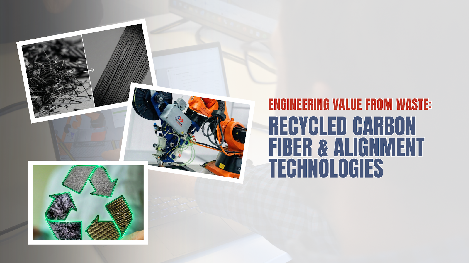
Recycled Carbon Fiber (rCF) in Semi-Structural Applications
A Review of Alignment Technologies and Discontinuous Fiber Micro-mechanics
Introduction
What happens when the aerospace industry's most prized material becomes its biggest waste problem? Over 60,000 tonnes of carbon fiber reinforced polymer (CFRP) waste accumulate annually worldwide, yet within these discarded structures lies a resource that retains up to 95% of its original strength. The emerging field of recycled carbon fiber (rCF) technology is transforming composite waste from an environmental liability into a strategic material opportunity—but only if we can solve the critical challenge of converting random, discontinuous fibers back into aligned, high-performance reinforcement.
This comprehensive review synthesizes findings from 23 peer-reviewed publications (2016-2025) to examine the state of rCF technology for semi-structural applications, focusing on the technologies that bridge the gap between waste and high-value composites.
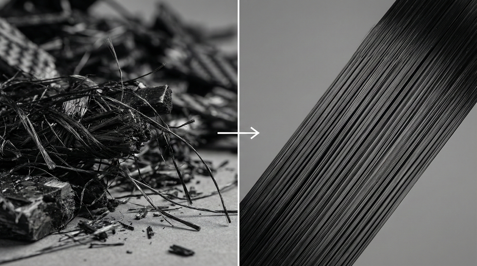
Carbon Fiber Reclamation & Alignment
Mixed-orientation fibers from
end-of-life composites
Unidirectional rCF tapes ready
for high-value remanufacture
The Carbon Fiber Paradox
The global carbon fiber reinforced polymer market continues its relentless expansion, driven by aerospace, automotive, wind energy, and sporting goods sectors. Yet this growth generates an increasingly urgent waste management challenge that threatens the very sustainability credentials that make composites attractive [1, 6].
KEY INSIGHT
Carbon fiber manufacturing consumes 183-286 MJ/kg and costs $20-30/kg for standard modulus fiber. Recycled carbon fibers retain 90-95% of original tensile strength and modulus when properly reclaimed, yet cost 50-70% less than virgin material [2, 6].
Scope of This Review
This review focuses specifically on four interconnected domains:
Fiber Reclamation Technologies — Thermal (pyrolysis) and chemical (solvolysis) methods for recovering fibers from composite waste.
Alignment Technologies — Methods to convert random rCF into oriented reinforcement suitable for structural applications.
Discontinuous Fiber Micro-mechanics — Stress transfer mechanisms and property prediction models for short-fiber composites.
Semi-Structural Applications — Automotive components, industrial structures, and other non-primary load-bearing applications.
The review does not cover continuous fiber recycling (re-spooling) or thermoplastic matrix recycling, focusing instead on the technically challenging domain of recovering and re-aligning short, discontinuous fibers.
Carbon Fiber Reclamation Technologies
Carbon Fiber Reclamation Technologies
The first critical challenge in the rCF value chain is fiber recovery from composite waste without compromising mechanical properties. Two principal pathways have emerged: thermal reclamation (pyrolysis) and chemical reclamation (solvolysis).
Pyrolysis: The Dominant Commercial Pathway
Pyrolysis remains the most commercially mature reclamation technology, with multiple industrial-scale operations now functioning worldwide [6, 12]. The process operates through thermal decomposition of the polymer matrix in an oxygen-depleted environment, typically at temperatures between 450-650°C.
Process Fundamentals
During pyrolysis, the polymer matrix undergoes thermal degradation while carbon fibers, with a decomposition temperature above 1000°C, remain largely intact [6]. Key process parameters include:
Property Retention
Research consistently demonstrates that pyrolyzed rCF retains 90-98% of virgin fiber tensile strength and modulus [2, 6, 12]. This retention occurs because the carbon fiber crystal structure remains essentially unaffected by temperatures below 650°C, though surface damage and sizing removal do occur.
Balaga et al. (2025) [7] demonstrated that recycled TuFF (Tow-preg) composites achieved 90% property retention when recycled from aligned short carbon fiber composites, confirming that proper processing can maintain high performance through multiple lifecycle iterations.
Surface Chemistry Considerations
The major limitation of pyrolysis is surface degradation. Virgin carbon fibers feature engineered surface treatments and sizing that promote adhesion to polymer matrices. Pyrolysis removes these surface functionalities, necessitating post-reclamation surface treatment for optimal composite performance [8, 23].
Ansari et al. (2025) [8] investigated microwave-assisted chemical recycling, demonstrating improved surface properties compared to conventional pyrolysis while maintaining mechanical performance. Their work highlighted that surface chemistry optimization represents a key pathway to enhancing rCF composite properties.
Solvolysis: The Surface-Preserving Alternative
Chemical reclamation through solvolysis offers potential advantages in surface preservation and fiber quality [20]. The process employs chemical solvents (typically under elevated temperature and pressure) to dissolve or depolymerize the matrix without thermal degradation.
Process Chemistry
Common solvolysis approaches include:
- Acid/base hydrolysis: Breaking polymer chains through chemical reaction
- Alcoholysis: Using alcohol solvents at elevated temperature/pressure
- Supercritical fluid extraction: Water or alcohol at supercritical conditions
Trukhinov et al. (2025) [20] explored low-temperature solvolysis efficiency, demonstrating carbon fiber extraction while minimizing energy consumption and environmental impact.
Advantages and Challenges
Solvolysis potentially offers several advantages over pyrolysis:
- Higher property retention: 95-100% of virgin fiber properties [6]
- Preserved surface chemistry: Sizing partially retained
- Lower processing temperature: 200-350°C typical
- Potential matrix recovery: Some solvents enable matrix reuse
However, commercial implementation faces challenges:
- Longer processing time (2-4 hours vs. <3 minutes for pyrolysis)
- Solvent handling and recovery requirements
- Higher operating costs
- More complex processing equipment
Comparative Analysis: Pyrolysis vs. Solvolysis
| Parameter | Pyrolysis | Solvolysis |
|---|---|---|
| Processing temperature | 450-650°C | 200-350°C |
| Processing time | <3 min | 2-4 hr |
| Fiber strength retention | 90-98% | 95-100% |
| Surface preservation | Poor | Good |
| Sizing retention | No | Partial |
| Energy consumption | Moderate | Lower |
| Solvent handling | None | Complex |
| Commercial maturity | High | Low-Medium |
| Operating cost | Lower | Higher |
| Matrix recovery | No | Possible |
TABLE 1: Source — Compiled from Gopalraj & Kärki (2020) [6], Pakdel et al. (2020) [12], Trukhinov et al. (2025) [20]
The Critical Fiber Quality Challenge
Regardless of reclamation method, recovered fibers emerge as randomly oriented, discontinuous material—typically 3-50mm in length depending on the original structure and reclamation process [6, 12]. This random, short-fiber form represents the critical barrier to high-performance composite production.
KEY CHALLENGE
Reclamation produces randomly oriented, short fibers (3-50mm length). Converting this random rCF into aligned, oriented reinforcement is essential for semi-structural applications. Without alignment, mechanical properties drop to 20-40% of continuous fiber performance [2, 15].
The next section examines technologies developed to address this fundamental challenge.
Fiber Alignment Technologies
Fiber Alignment Technologies
Converting random rCF into aligned reinforcement represents the critical value-added processing step that enables semi-structural applications. Multiple alignment approaches have been developed, each with distinct capabilities, throughput characteristics, and alignment efficiency.
Carding and Needling: The Textile Approach
Adapted from textile processing, carding and needling represent established, high-throughput methods for fiber alignment [2, 14, 15].
Process Description
The carding process passes fibers through rotating cylinders with fine teeth that partially align fibers in the machine direction. Subsequent needling can consolidate layers into nonwoven mats with controlled thickness and areal weight.
Cheng et al. (2024) [2] investigated optimization of carding and layup parameters for recycled carbon fiber mats, demonstrating that alignment significantly influences both mechanical and electromagnetic shielding properties. Their work showed that 0°/90° layup configurations could achieve quasi-isotropic mechanical properties while maintaining excellent EMI shielding effectiveness (>30 dB).
Performance Characteristics
Van de Werken et al. (2017) [15] demonstrated that carded rCF mats achieved tensile modulus of 40-50 GPa and strength of 400-500 MPa in aligned direction—representing approximately 50-60% of continuous fiber performance.
Limitations
- Fiber damage during processing (particularly for shorter fibers <10mm)
- Limited alignment efficiency compared to advanced methods
- Difficulty handling very short fibers (<5mm)
- Equipment adaptation required for carbon fiber processing
Hydrodynamic Alignment: The HiPerDiF Method
The High Performance Discontinuous Fiber (HiPerDiF) method, developed at the University of Bristol, represents a breakthrough in alignment technology [14, 18].
Process Fundamentals
HiPerDiF suspends fibers in a water-based slurry, then passes the suspension through a converging channel onto a moving substrate. Hydrodynamic forces align fibers as the flow narrows, producing highly oriented fiber tapes or preforms.
Longana et al. (2018) [14] developed comprehensive quality control methodologies for HiPerDiF-processed materials, demonstrating alignment efficiencies of 75-85% with excellent repeatability and process control.
Key Advantages
- High alignment efficiency: 75-85% of fibers oriented within ±10°
- Fiber length preservation: Minimal fiber damage
- Variable areal weight: Precise control through processing parameters
- Direct-to-substrate deposition: Enables complex geometries
Sato et al. (2025) [3] utilized highly oriented recycled carbon fiber composites produced via similar hydrodynamic alignment, achieving mechanical properties approaching those of virgin continuous fiber composites when processed through optimized molding methods.
Scaling Considerations
The primary challenge for HiPerDiF and similar hydrodynamic methods is production rate scaling. While laboratory systems demonstrate excellent fiber alignment, industrial-scale continuous processing requires significant development in water handling and recycling, drying and consolidation, throughput optimization, and multi-station processing.
Dry Mechanical Alignment Methods
Various dry mechanical alignment techniques have been investigated to avoid wet processing challenges [16].
Miyake & Imaeda (2016) [16] developed a dry aligning method using air flow and vibration to orient discontinuous carbon fibers. Their method achieved:
The dry mechanical approach offers manufacturing advantages through faster processing (no drying required), simpler equipment, lower environmental impact, and direct integration with composite molding.
However, alignment efficiency typically lags behind optimized wet methods, and controlling areal weight uniformity presents challenges at high throughput.
TuFF Technology: The Gold Standard
The Tailorable Universal Feedstock for Forming (TuFF) technology, developed by Solvay and now commercialized, represents the current state-of-the-art in rCF alignment [5, 7].
Technology Overview
TuFF produces aligned discontinuous fiber tapes by carefully spreading and aligning short fibers into a matrix-impregnated tow, creating a material form functionally similar to continuous fiber tow-preg but from discontinuous feedstock.
Ozdemir et al. (2024) [5] provided comprehensive documentation of carbon fiber composite recycling enabled by TuFF technology, demonstrating:
Performance Validation
Balaga et al. (2025) [7] optimized the recycling process for aligned short carbon fiber TuFF composites, achieving remarkable circular lifecycle performance:
- First recycling cycle: 90% property retention
- Second recycling cycle: 85% property retention
- Minimal degradation with proper processing control
This multi-cycle performance demonstrates that TuFF technology enables truly circular composite manufacturing, where materials can be repeatedly reclaimed, re-aligned, and reprocessed without catastrophic property loss.
Commercial Viability
TuFF technology bridges the gap between laboratory research and industrial implementation through standard composite manufacturing compatibility, automated fiber placement (AFP) compatibility, consistent material properties, and qualified supply chain integration.
However, the technology requires sophisticated processing equipment and currently operates at lower throughput than continuous fiber production.
Comparative Performance Analysis
| Technology | Alignment | Modulus (GPa) | Strength (MPa) | Throughput | Complexity |
|---|---|---|---|---|---|
| Random rCF | ~20% | 15-25 | 150-250 | N/A | Low |
| Carding/Needling | 60-75% | 40-50 | 400-500 | High | Medium |
| Hydrodynamic (HiPerDiF) | 75-85% | 55-75 | 600-900 | Medium | High |
| Dry Mechanical | 70-80% | 50-65 | 500-700 | Med-High | Medium |
| TuFF Technology | >90% | 70-95 | 800-1200 | Medium | High |
| Virgin CF (reference) | ~100% | 120-150 | 1500-2000 | High | Low |
TABLE 2: Sources — Compiled from van de Werken et al. (2017) [15, 17], Longana et al. (2018) [14], Miyake & Imaeda (2016) [16], Ozdemir et al. (2024) [5], Balaga et al. (2025) [7]
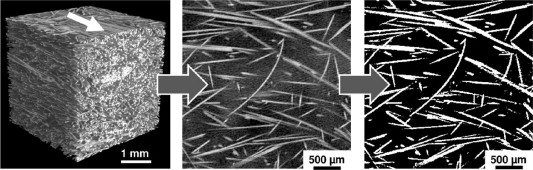
Discontinuous Fiber Micro-mechanics
Stress Transfer in Discontinuous Fiber Composites
For carbon fiber / epoxy systems
Understanding the micro-mechanics of discontinuous fiber composites is fundamental to predicting and optimizing rCF composite performance. Unlike continuous fiber composites where stress transfer is direct and uniform, short fiber composites rely on interfacial shear to transfer load from matrix to fiber.
Critical Length and Stress Transfer Efficiency
The fundamental concept governing short fiber composite mechanics is the critical fiber length (ℓc)—the minimum length required for a fiber to develop maximum stress before failure.
Kelly-Tyson Analysis
For a fiber embedded in a matrix and loaded in tension, stress builds up from the fiber ends through interfacial shear stress (τi). The critical length is given by:
ℓc = (σf × d) / (2 × τi)
Where: σf = fiber tensile strength, d = fiber diameter, τi = interfacial shear strength
For typical carbon fiber/epoxy systems:
Length Efficiency Factor
The length efficiency factor (ηℓ) quantifies how effectively a discontinuous fiber carries load relative to a continuous fiber:
For ℓ < ℓc: ηℓ = ℓ / (2ℓc)
For ℓ ≥ ℓc: ηℓ = 1 - (ℓc / 2ℓ)
This relationship demonstrates why fiber length distribution critically influences composite properties. For rCF with typical lengths of 5-25mm:
Orientation Efficiency and the Krenchel Model
Fiber orientation distribution profoundly affects composite stiffness and strength. The Krenchel orientation efficiency factor (η₀) accounts for the statistical distribution of fiber orientations:
η₀ = Σ (aᵢ × cos⁴θᵢ)
Where: aᵢ = fraction of fibers at angle θᵢ, θᵢ = angle from loading direction
Characteristic Orientation States
Fiber Orientation States & Efficiency
For typical rCF alignment states:
These orientation factors directly multiply composite stiffness and strength, explaining why alignment is critical for structural performance.
Combined Efficiency: The Modified Rule of Mixtures
Integrating length and orientation effects, the modified rule of mixtures for short fiber composite longitudinal modulus becomes:
Ec = ηℓ × η₀ × Vf × Ef + (1 - Vf) × Em
Where: Ec = composite modulus, ηℓ = length efficiency factor, η₀ = orientation efficiency factor, Vf = fiber volume fraction, Ef = fiber modulus, Em = matrix modulus
Example Calculation
For a typical rCF composite with: Fiber modulus: Ef = 230 GPa, Matrix modulus: Em = 3 GPa, Fiber volume fraction: Vf = 40%, Fiber length: 15mm (ηℓ = 0.93), High alignment: (η₀ = 0.85)
Ec = 0.93 × 0.85 × 0.40 × 230 + 0.60 × 3 = 75.3 GPa
This compares to theoretical continuous fiber composite: Ec (continuous) = 1.0 × 1.0 × 0.40 × 230 + 0.60 × 3 = 93.8 GPa
The discontinuous fiber composite achieves 80% of continuous fiber stiffness, primarily limited by orientation distribution rather than fiber length effects.
Interfacial Considerations for rCF
The interfacial shear strength (τi) critically governs stress transfer efficiency, making surface treatment essential for recycled fibers [8, 23].
Surface Chemistry Challenges
Pyrolysis removes virgin fiber sizing, reducing interfacial bonding. Yatim (2020) [23] investigated oxidation of reclaimed carbon fiber surfaces, demonstrating that controlled surface treatment can restore interfacial adhesion to near-virgin levels.
Ansari et al. (2025) [8] showed that microwave-assisted chemical recycling preserves better surface characteristics than conventional pyrolysis, resulting in improved interfacial properties and composite performance.
Sizing and Surface Treatments
Post-reclamation surface treatments include:
- Oxidative treatments: Introducing surface functional groups
- Plasma treatments: Modifying surface chemistry and roughness
- Sizing application: Applying commercial or custom sizing agents
- Coupling agents: Using silanes or other bonding promoters
van de Werken (2017) [17] systematically investigated the effect of sizing on recycled carbon fiber composite properties, demonstrating that appropriate sizing selection can enhance interfacial shear strength by 30-50% compared to unsized rCF.
Mechanical Properties of rCF Composites
Mechanical Property Retention vs. Virgin CF Composites
The mechanical performance of rCF composites depends critically on fiber quality, alignment state, processing method, and fiber-matrix interface optimization. This section synthesizes experimental data from recent literature to establish realistic performance expectations.
Tensile Properties
Modulus
Sato et al. (2025) [3] evaluated highly oriented rCF composites produced via vacuum-assisted resin transfer molding (VARTM), wet-layup, and resin transfer molding (RTM), achieving:
These results demonstrate that processing method significantly affects property translation, with pressure-assisted molding (VARTM, RTM) providing superior consolidation and fiber wet-out.
For highly aligned TuFF materials, Ozdemir et al. (2024) [5] reported tensile modulus values of 75-90 GPa, representing 65-78% of equivalent continuous fiber composites.
Strength
Tensile strength retention generally lags modulus retention due to stress concentration at fiber ends and the statistical nature of failure in discontinuous systems.
Van de Werken (2017) [17] systematically characterized aligned rCF composites produced through different methods:
The dramatic influence of sizing confirms the critical role of interfacial adhesion in translating fiber properties to composite performance.
Flexural Properties
Flexural testing provides insight into composite behavior under bending loads, combining tensile, compressive, and shear contributions.
Cheng et al. (2024) [2] investigated layup optimization of carded rCF mats, demonstrating that quasi-isotropic layup (0°/90°) provided balanced flexural properties:
For highly aligned rCF, flexural modulus typically reaches 60-80 GPa, approaching or exceeding values for random continuous fiber mats (typically 40-60 GPa).
Compression Properties
Compression strength represents a critical design parameter for semi-structural applications, yet receives less research attention than tensile properties.
The discontinuous nature of rCF can actually benefit compression performance by reducing susceptibility to fiber buckling compared to continuous fiber composites. Compression strength retention is typically 75-85% of tension strength retention for equivalent alignment states.
Impact and Damage Tolerance
One of the most promising characteristics of rCF composites is superior impact resistance and damage tolerance compared to continuous fiber composites.
Energy Absorption Mechanisms
Discontinuous fiber architecture provides multiple energy dissipation mechanisms:
- Fiber-matrix debonding (controlled by interfacial strength)
- Fiber pull-out (length-dependent)
- Matrix cracking and deformation
- Inter-fiber friction
Barnett et al. (2023) [4] investigated crashworthiness of rCF composite sinusoidal structures at dynamic rates, demonstrating:
This damage tolerance makes rCF particularly attractive for automotive crashworthiness applications where controlled energy absorption is desired.
Newman et al. (2022) [19] explored high-value applications beyond conventional structural uses, demonstrating rCF composite performance in environmental remediation applications while maintaining excellent mechanical properties for subsequent structural redeployment.
Multi-functional Properties
Electromagnetic Shielding
Cheng et al. (2024) [2] demonstrated that aligned rCF mats provide excellent electromagnetic interference (EMI) shielding effectiveness:
- Shielding effectiveness: >30 dB across 8-12 GHz
- Performance maintained with quasi-isotropic layup
- Competitive with virgin CF composites
Enhanced Properties Through Hybridization
Sharma & Zafar (2025) [10] investigated enhancement of rCF composites through graphene nanoplatelet integration, achieving 15-25% improvement in mechanical properties, enhanced electrical conductivity, and improved thermal management.
Chahine et al. (2025) [9] explored hybridization of glass sheet molding compounds (SMC) with rCF, demonstrating synergistic benefits: cost reduction through selective rCF reinforcement, maintained structural performance, and improved sustainability metrics.
Processing Method Effects
The manufacturing process dramatically influences property translation from fiber to composite.
| Method | Typical Vf | Void % | Modulus (GPa) | Strength (MPa) | Advantages |
|---|---|---|---|---|---|
| Hand layup | 30-40% | 3-8% | 35-55 | 400-600 | Simple, low cost |
| VARTM | 40-50% | 1-4% | 55-70 | 600-850 | Good consolidation |
| RTM | 45-55% | 0.5-2% | 65-80 | 700-1000 | Excellent properties |
| Compression molding | 40-50% | 1-3% | 50-75 | 550-900 | High throughput |
| Additive mfg. | 15-30% | 5-15% | 20-40 | 250-450 | Design freedom |
TABLE 3: Sources — Sato et al. (2025) [3], van de Werken (2017) [17], Ueda et al. (2025) [11]
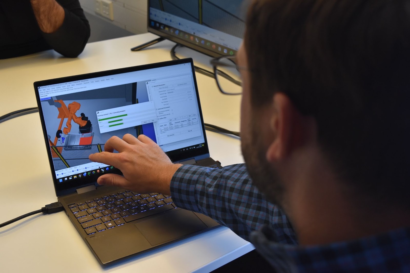
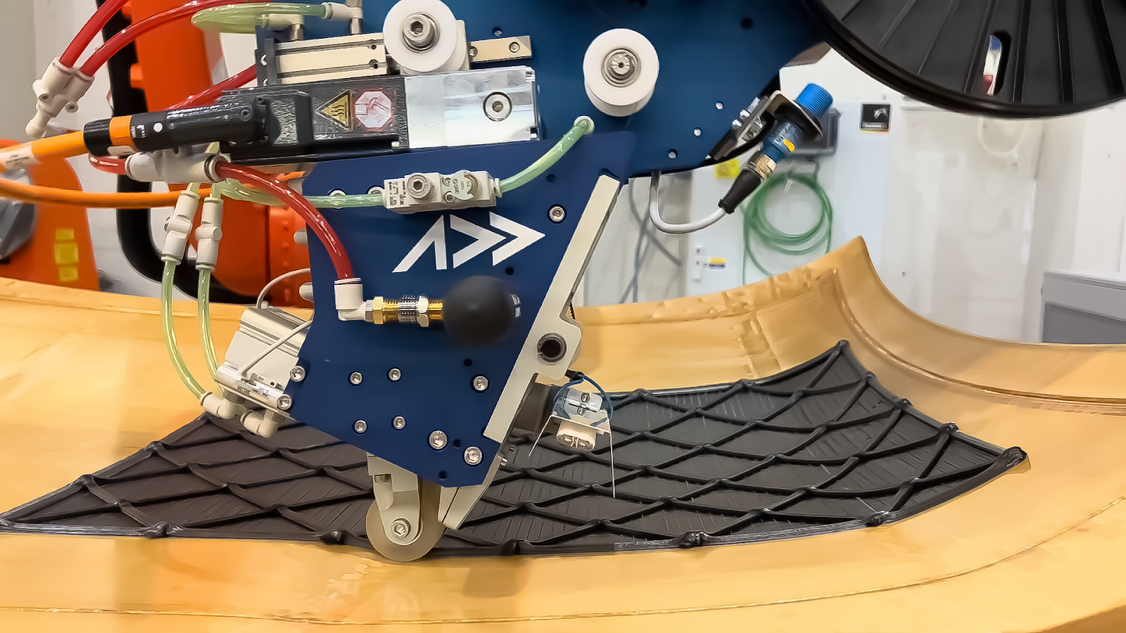
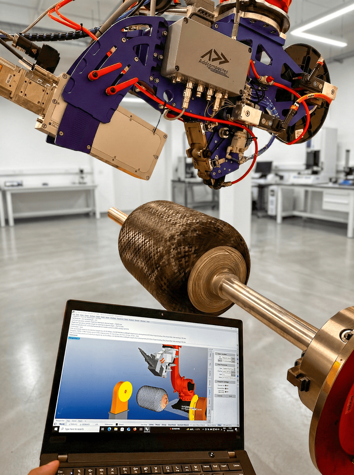
AddPath path planning software optimizes rCF tape placement for maximum property retention, making precision AFP accessible for semi-structural component production.
Additive Manufacturing with rCF
Ueda et al. (2025) [11] explored three-dimensional printing of recycled carbon fiber spun yarn-reinforced polyamide, demonstrating feasibility of rCF in additive manufacturing: successful fiber incorporation in thermoplastic matrices, maintained fiber alignment during extrusion, and achieved reinforcement efficiency in printed parts.
This application domain opens new possibilities for complex geometry rCF components, though mechanical properties lag compression-molded parts due to lower fiber volume fraction and higher void content.
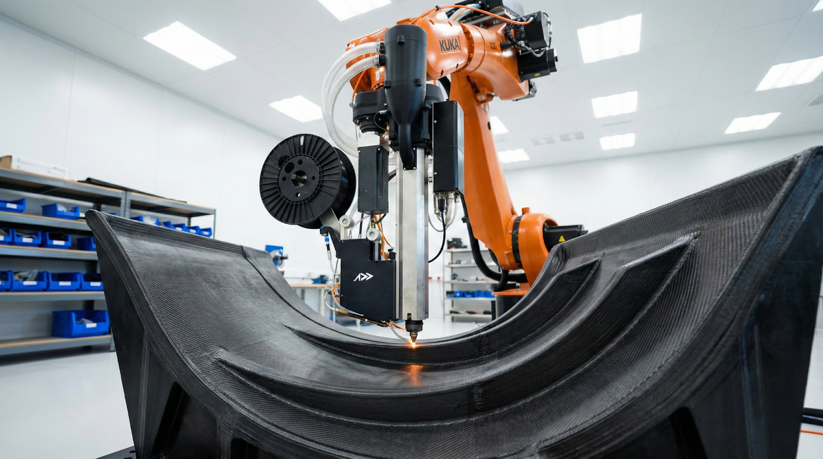
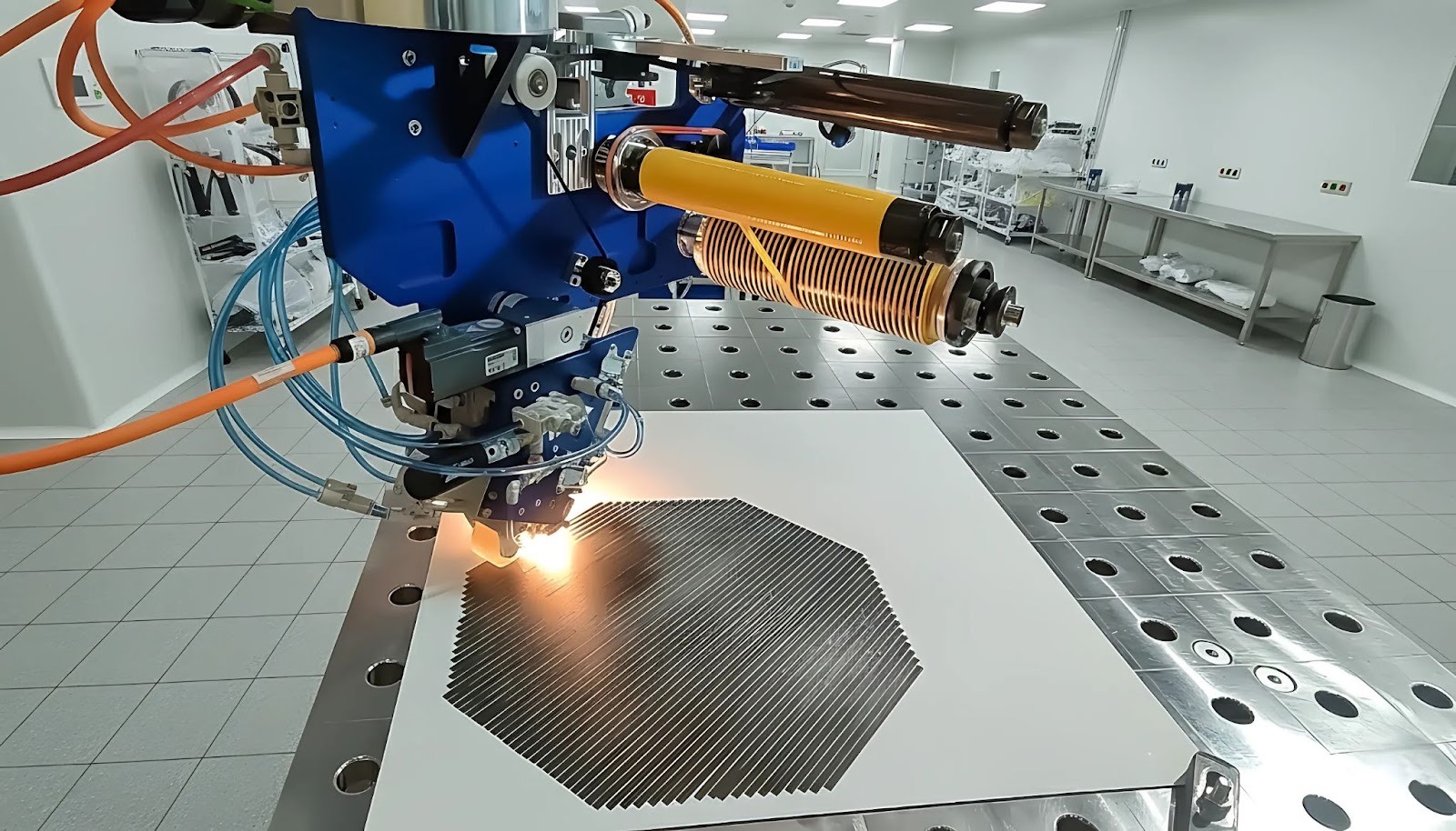
ADDX large format additive manufacturing with parallel polymer-fiber extrusion enables recycled carbon fiber integration in complex geometries for semi-structural applications.
Semi-Structural Applications
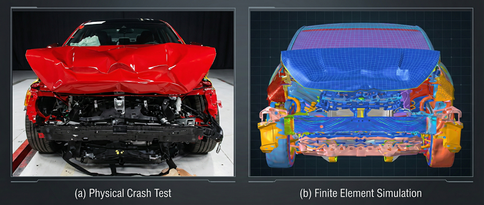
rCF Composite Crashworthiness Performance
Semi-structural applications represent components that carry loads but are not primary load-bearing structures. These applications tolerate lower safety factors than aerospace primary structures while demanding significantly higher performance than purely cosmetic parts.
Automotive Applications: The Primary Market
The automotive industry represents the most promising near-term market for rCF composites, driven by lightweighting demands, sustainability mandates, and cost pressures.
Crashworthiness Components
Barnett et al. (2023) [4] demonstrated that rCF composites excel in crashworthiness applications through:
Target applications include: crash boxes and energy absorbers, B-pillar reinforcements, front and rear bumper beams, and side impact protection structures.
Body Panels and Closure Elements
Meng et al. (2017) [1] conducted comprehensive environmental assessment of rCF use in automotive applications, demonstrating favorable life-cycle impacts for hood panels, roof panels, deck lids and lift gates, and door inner structures.
The study showed 40-60% reduction in carbon footprint compared to virgin CF while maintaining structural performance.
Battery Enclosures
Electric vehicle battery enclosures represent a rapidly growing application where rCF composites offer multiple benefits:
- Structural stiffness for battery protection
- Electromagnetic shielding (demonstrated by Cheng et al. [2])
- Thermal management capabilities
- Weight reduction (15-25% vs. steel structures)
- Fire resistance
Under-body Structures
Chahine et al. (2025) [9] demonstrated hybridization of glass SMC with rCF for automotive under-body components, achieving 20-30% weight reduction vs. glass-only SMC, maintained stiffness requirements, 30-40% cost reduction vs. virgin CF, and high-volume manufacturing compatibility.
Industrial and Commercial Applications
Wind Energy
The wind energy sector generates substantial composite waste and provides a natural application for rCF: non-structural fairings and nacelle covers, secondary load-bearing components, blade trailing edge reinforcement, and service and access structures.
Abdi et al. (2025) [18] reviewed recycling and remanufacturing of semi-long and long carbon fibers, highlighting wind turbine decommissioning as a major future feedstock source while identifying blade spar components as potential rCF application targets.
Marine Structures
Marine applications leverage rCF's corrosion resistance and damage tolerance: bulkheads and interior structures, non-wetted hull sections, deck structures and hatches, and equipment housings.
Infrastructure
Civil engineering applications include: bridge deck panels, seismic retrofitting elements, architectural cladding systems, and protective barriers.
Sports and Consumer Goods
High-performance sporting goods represent established markets for advanced composites, with rCF enabling cost-competitive high-performance products: bicycle frames and components, ski and snowboard structures, racquet sports equipment, and protective equipment.
The shorter product lifecycles and lower safety criticality in sporting goods facilitate faster rCF adoption compared to aerospace or automotive sectors.
Economic and Environmental Considerations
rCF Economic & Environmental Value Proposition
The business case for rCF adoption rests on both economic and environmental pillars. Understanding the value proposition requires examining costs across the entire lifecycle.
Economic Analysis
Fiber Cost Comparison
Virgin carbon fiber production involves energy-intensive precursor synthesis, stabilization, and carbonization, resulting in:
Recycled carbon fiber costs vary with reclamation method and processing state:
Even highly processed aligned rCF costs 40-60% less than virgin standard modulus fiber while delivering 70-90% of mechanical performance.
System-Level Economic Assessment
Meng et al. (2017) [1] conducted comprehensive system-level cost analysis for automotive rCF applications, concluding:
The economic viability improves as reclamation capacity scales up (economy of scale), waste feedstock becomes more readily available, alignment processing technology matures, and carbon pricing mechanisms incentivize recycling.
Manufacturing Integration Costs
Transitioning existing composite manufacturing to rCF involves process qualification and validation, material characterization and testing, supply chain development, and quality assurance system implementation.
These transition costs are offset by lower material costs (40-60% reduction), existing equipment compatibility (especially for TuFF-type materials), and sustainability benefits enabling market access.
Environmental Life Cycle Assessment
Embodied Energy Comparison
Virgin carbon fiber is one of the most energy-intensive structural materials:
Recycled carbon fiber dramatically reduces embodied energy:
Even including alignment processing, rCF requires 80-85% less energy than virgin CF production.
Carbon Footprint
Gopalraj & Kärki (2020) [6] synthesized life cycle assessment data demonstrating:
For perspective, producing 1,000 kg of rCF avoids approximately 25 tonnes of CO₂ emissions compared to virgin fiber.
Waste Diversion
The composite industry generates approximately 60,000 tonnes of CFRP waste annually [6], with projections reaching 100,000+ tonnes/year by 2030 as first-generation wind turbines and aircraft reach end-of-life.
Current rCF production diverts only ~8% of this waste stream. Scaling rCF adoption to 40-50% waste capture by 2030 would divert 25,000-30,000 tonnes from landfill annually, avoid 500,000-750,000 tonnes CO₂-eq emissions, and reduce virgin fiber demand by 30-40%.
Circular Economy Integration
Material Cascade Strategy
Optimal rCF utilization follows a material cascade:
- First lifecycle: Aerospace primary structure (virgin CF)
- Second lifecycle: Automotive semi-structural (high-alignment rCF)
- Third lifecycle: Consumer goods or non-structural (lower-grade rCF)
- Fourth lifecycle: Energy recovery or chemical recycling
Balaga et al. (2025) [7] demonstrated this concept through multiple recycling cycles of TuFF composites, showing first recycle at 90% property retention and second recycle at 85% property retention, with potential for 3-4 lifecycle iterations. This enables 50-100 years of material service life from a single fiber production cycle.
Closed-Loop Supply Chains
Emerging business models include aerospace → automotive material cascades, composite manufacturer take-back programs, industrial symbiosis networks (waste becomes feedstock), and distributed reclamation and alignment facilities.
Current Challenges and Knowledge Gaps
Despite significant progress in rCF technology, critical challenges remain that must be addressed to enable widespread industrial adoption.
Technical Challenges
Fatigue Performance Uncertainty
The most significant knowledge gap is long-term fatigue behavior. While static mechanical properties are well-characterized, fatigue performance under cyclic loading remains poorly understood:
- Limited fatigue data for aligned rCF composites
- Uncertainty in S-N curve prediction models
- Unknown impact of fiber-end stress concentrations
- Variable performance with processing conditions
For semi-structural applications with fatigue-critical loading (automotive suspension components, wind turbine structures), this uncertainty prevents design certification.
Property Variability and Quality Control
rCF feedstock variability creates challenges:
- Varying fiber length distributions (dependent on source material)
- Inconsistent fiber quality (dependent on reclamation process)
- Mixed fiber types in waste streams (T300 vs. T700 vs. IM fibers)
- Unknown service history (stress exposure, environmental aging)
Longana et al. (2018) [14] developed quality control methodologies for HiPerDiF processing, but industry-wide standards remain absent.
Processing Scale-Up
Most alignment technologies demonstrate excellent performance at laboratory scale but face challenges in continuous, high-throughput production:
Bridging the gap from 10-50 kg/day laboratory systems to 1,000+ kg/day industrial production requires significant development.
Material Science Challenges
Fiber Length Optimization
The optimal fiber length for different applications and processing methods remains unclear:
- Shorter fibers (5-10mm): Easier processing, lower properties
- Medium fibers (10-20mm): Balanced processing and performance
- Longer fibers (20-50mm): Higher properties, processing challenges
Length distribution control during reclamation and subsequent processing represents an active research area.
Interface Engineering
Achieving virgin-fiber-equivalent interfacial adhesion requires optimized surface treatments for pyrolyzed fibers, sizing chemistry development for rCF, process control for consistent surface chemistry, and understanding of aging effects on treated surfaces.
Ansari et al. (2025) [8] and Yatim (2020) [23] have made progress, but commercial surface treatment processes remain underdeveloped.
Hybrid Material Systems
Combining rCF with other reinforcements (glass fiber, natural fibers, virgin CF) offers potential benefits but requires understanding: optimal hybrid ratios for different applications, processing compatibility of dissimilar fibers, interface compatibility in multi-fiber systems, and failure mode interactions.
Chahine et al. (2025) [9] and Sharma & Zafar (2025) [10] have explored these systems, but design guidelines remain preliminary.
Economic and Industrial Challenges
Supply Chain Development
Establishing reliable rCF supply chains requires waste collection and aggregation logistics, quality assurance across multiple processing steps, traceability systems for fiber provenance, and inventory management for variable feedstock.
Certification and Standardization
The absence of industry standards creates barriers: no standardized test methods for rCF characterization, lack of material specifications and datasheets, undefined qualification processes for semi-structural applications, and regulatory uncertainty in aerospace applications.
Market Development
Creating demand for rCF products involves educating designers and engineers on rCF capabilities, developing design guidelines and property databases, demonstrating long-term field performance, and overcoming negative perceptions about recycled materials.
Environmental and Social Challenges
True Circularity
Achieving closed-loop circularity requires addressing matrix recycling (currently limited to pyrolysis byproducts), multi-cycle fiber property degradation limits, ultimate disposal pathways after 3-4 lifecycles, and chemical recycling to monomers as final pathway.
Equitable Development
Ensuring rCF benefits are broadly distributed: access to recycling infrastructure globally, fair labor practices in waste collection, avoiding "waste colonialism" (shipping waste to developing nations), and supporting local manufacturing capacity.
Future Directions
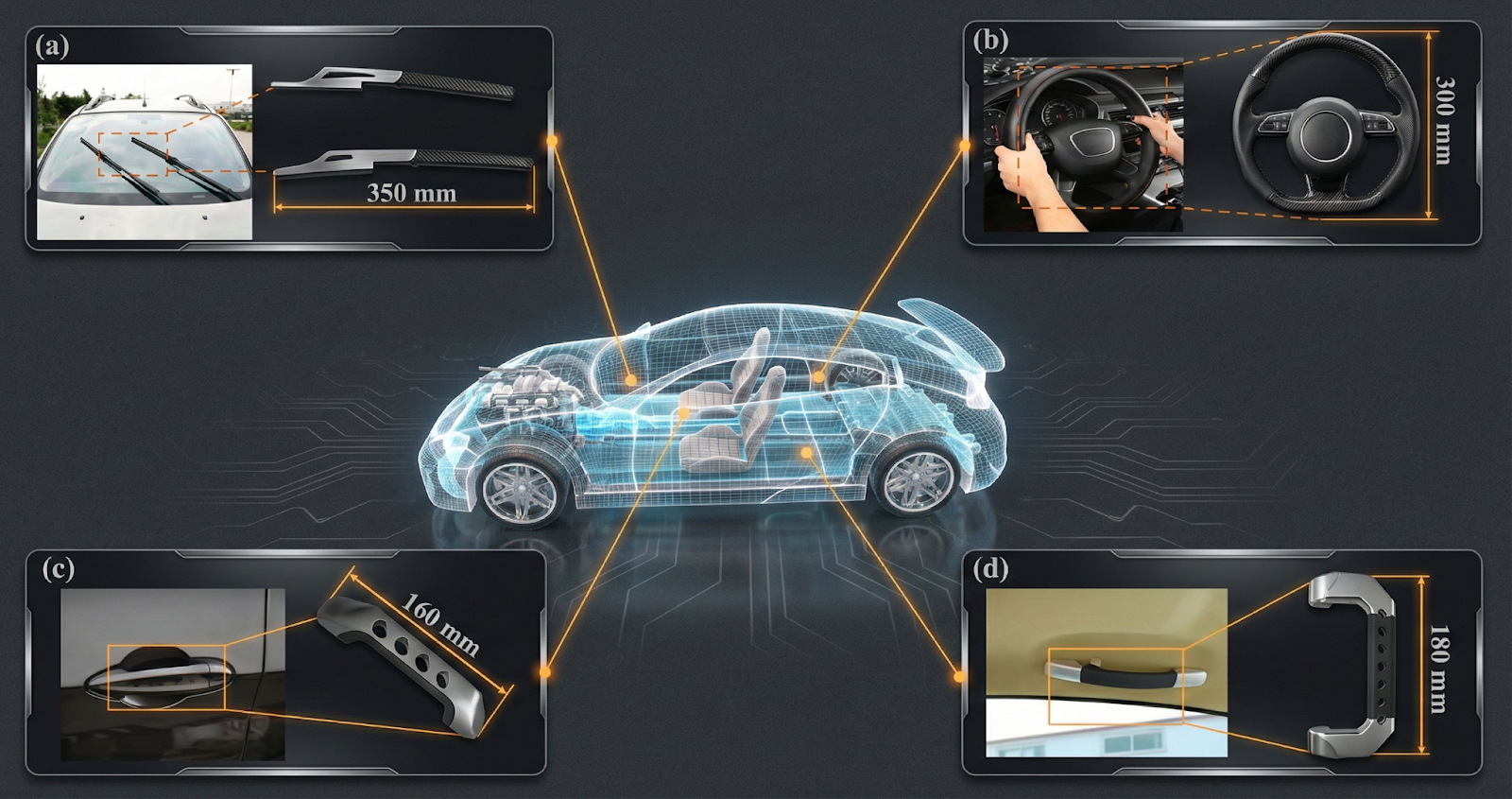
Automotive rCF Application Map
Automotive applications range from primary structures (virgin CF) to semi-structural (high-alignment rCF), non-structural (moderate-alignment rCF), and functional components like EMI shielding (carded rCF acceptable).
Automotive rCF Application Map
The field of recycled carbon fiber composites stands at an inflection point. Technological foundations are established, initial markets are developing, and environmental pressures are intensifying. Several key developments will shape the next decade.
Technology Development Trajectories
Advanced Alignment Systems
Next-generation alignment technologies will focus on:
- Continuous, high-throughput processing: Scaling HiPerDiF and TuFF-type systems to >1,000 kg/day
- Multi-axis orientation control: Creating complex fiber orientation distributions for specific load cases
- In-line quality monitoring: Real-time alignment measurement and process control
- Hybrid processing: Combining alignment methods for optimized cost-performance balance
Digital Manufacturing Integration
Industry 4.0 technologies will enable:
- Digital twins: Real-time process monitoring and optimization
- AI-driven quality control: Automated defect detection and property prediction
- Additive manufacturing: Direct-write processes with aligned rCF reinforcement (building on Ueda et al. [11])
- Automated layup: Robotic placement of rCF tapes and preforms
Application Expansion
Automotive Electrification
Electric vehicles will drive rCF adoption through battery enclosures (structural, thermal, and EMI shielding requirements), motor housings (electromagnetic compatibility and thermal management), structural integration (battery-as-structure concepts using rCF), and lightweight components (extending vehicle range through mass reduction).
Aerospace Secondary Structures
While primary structures will likely remain virgin CF domain, rCF can address interior structures (seat frames, stowage bins, floor panels), non-structural fairings (access panels, inspection covers), ground support equipment (tooling, jigs, fixtures), and satellite components (non-critical structures for cost reduction).
Wind Energy Expansion
As first-generation turbines reach end-of-life (2025-2035), enormous rCF feedstock will become available. Applications include second-generation blade structures, tower reinforcement (hybrid concrete-rCF), nacelle components (covers, structural supports), and foundation elements (marine structure reinforcement).
Policy and Regulatory Development
Extended Producer Responsibility
Evolving regulations will likely mandate composite manufacturer take-back programs, recycled content requirements in new products, disposal fees for non-recycled composite waste, and certification systems for rCF quality and provenance.
Carbon Pricing and Incentives
Economic instruments promoting rCF adoption: carbon border adjustment mechanisms favoring low-carbon materials, subsidies for rCF processing infrastructure, tax incentives for rCF utilization, and green procurement policies.
Standardization Initiatives
Development of certification approaches for aerospace non-primary structures and automotive applications.
Circular Economy Integration
The rCF industry sits at the nexus of composite manufacturing, waste management, and circular economy initiatives. Successful development requires coordination across composite manufacturers (waste generators), recyclers and reclaimers, alignment/processing technology providers, end-product manufacturers, and policy makers and regulators.
The Bottom Line
Here's what you need to know:
Fiber reclamation is commercially viable, with pyrolysis offering the most mature pathway (90-98% strength retention) and solvolysis showing promise for superior surface preservation.
Alignment technologies can convert random rCF into oriented reinforcement achieving 70-90% of continuous fiber properties, with TuFF and hydrodynamic methods achieving >90% alignment efficiency.
Economics favor rCF adoption with 50-70% cost reduction versus virgin fiber and 70-90% energy savings in production.
Automotive semi-structural applications represent the primary near-term market, with crashworthiness, body panels, and battery enclosures as key targets.
Critical knowledge gaps remain in fatigue performance, standardized testing protocols, and production-scale alignment processing.
The transition from laboratory to industrial scale is underway, with multiple companies now offering commercial rCF products and alignment technologies.
The composite industry stands at an inflection point. As first-generation carbon fiber structures reach end-of-life and sustainability pressures intensify, recycled carbon fiber offers a pathway to close the loop—transforming waste into resource while maintaining the performance advantages that made composites essential in the first place.
Methodology Note
This review was compiled from 23 peer-reviewed publications identified through systematic search of academic databases including Semantic Scholar and OpenAlex. Selection criteria included relevance to recycled carbon fiber, fiber alignment, discontinuous fiber mechanics, and semi-structural applications. The review covers publications from 2016-2025, with emphasis on recent developments (2020-2025).
References
[1] Meng, F., McKechnie, J., Turner, T., Wong, K., & Pickering, S. (2017). Environmental Aspects of Use of Recycled Carbon Fiber Composites in Automotive Applications. Environmental Science & Technology, 51(21), 12727-12736.
[2] Cheng, H., Wang, Q., Guo, L., Zhou, J., Tang, M., Zhai, H., Wang, H., & Qian, Z. (2024). Investigation of alignment and layup optimization of recycled carbon fiber mats on mechanical and electromagnetic shielding properties of composites. Polymer Composites, 45(7).
[3] Sato, M., Kataoka, Y., Higashide, M., Ishida, Y., & Sugimoto, S. (2025). Evaluation of the Mechanical Properties of Highly Oriented Recycled Carbon Fiber Composites Using the Vacuum-Assisted Resin Transfer Molding, Wet-Layup, and Resin Transfer Molding Methods. Polymers, 17(10), 1293.
[4] Barnett, P.R., Vigna, L., Martínez-Collado, J.L., Calzolari, A., & Penumadu, D. (2023). Crashworthiness of recycled carbon fiber composite sinusoidal structures at dynamic rates. Composite Structures, 312, 116847.
[5] Ozdemir, T., Deitzel, J., Crane, R., Yarlagadda, S., Blackwell, C., Davis, M., Emmerich, R., & Heider, D. (2024). Carbon Fiber Composites Recycling Technology Enabled by the TuFF Technology. Recycling, 9(1), 11.
[6] Gopalraj, S.K. & Kärki, T. (2020). A review on the recycling of waste carbon fibre/glass fibre-reinforced composites: fibre recovery, properties and life-cycle analysis. SN Applied Sciences, 2, 433.
[7] Balaga, U.K., Gunes, A., Ozdemir, T., Blackwell, C., Davis, M., Sauerbrunn, S., Fuessel, L., Deitzel, J., & Heider, D. (2025). Optimization of the Recycling Process for Aligned Short Carbon Fiber TuFF Composites. Recycling, 10(2), 55.
[8] Ansari, M.S., Zafar, S., Pathak, H., & Anand, A. (2025). Effect of Microwave Assisted Chemical Recycling Process on Surface Properties and Mechanical Performance of Recycled Carbon Fiber. Fibers and Polymers, 26.
[9] Chahine, G., Meraki, Y., Barakat, A., Hess, J., Fono Tamo, R.F., & Vaidya, U. (2025). Hybridizing of glass sheet molding compounds (SMC) with recycled carbon fiber (rCF). Journal of Composite Materials.
[10] Sharma, A. & Zafar, S. (2025). Enhancing Multifunctional Properties of Recycled Carbon Fiber Composites Through Graphene Nanoplatelet Integration. Polymer Composites.
[11] Ueda, M., Sato, K., Ichihara, N., Matsumoto, Y., & Nagai, S. (2025). Three-dimensional printing of recycled carbon fiber spun yarn reinforced polyamide. Journal of Thermoplastic Composite Materials.
[12] Pakdel, E., Kashi, S., Varley, R.J., & Wang, X. (2020). Recent progress in recycling carbon fibre reinforced composites and dry carbon fibre wastes. Resources, Conservation and Recycling, 166, 105340.
[13] Nag, M. & Shrivastava, A. (2023). Characterization and performance evaluation of nylon-66 composite at various composition of carbon fibers and GNP reinforcement. Journal of Plastic Film & Sheeting, 40(2).
[14] Longana, M., Yu, H., Hamerton, I., & Potter, K. (2018). Development and application of a quality control and property assurance methodology for reclaimed carbon fibers based on the HiPerDiF method and interlaminated hybrid specimens. Advanced Manufacturing: Polymer & Composites Science, 4(2), 48-55.
[15] van de Werken, N., Allred, R., & Tehrani, M. (2017). Effect of Alignment and Sizing on Mechanical Properties of Discontinuous Recycled Carbon Fiber Composites. Proceedings of the American Society for Composites.
[16] Miyake, T. & Imaeda, S. (2016). A dry aligning method of discontinuous carbon fibers and improvement of mechanical properties of discontinuous fiber composites. Advanced Manufacturing: Polymer & Composites Science, 2(3-4), 117-123.
[17] van de Werken, N. (2017). Effect of Alignment, Sizing, and Manufacturing Method on Mechanical Properties of Recycled Carbon Fiber Composites. Master's Thesis, University of New Mexico.
[18] Abdi, B., Wang, Y., Gong, H., & Su, M. (2025). Recycling, Remanufacturing and Applications of Semi-Long and Long Carbon Fibre from Waste Composites: A Review. Applied Composite Materials.
[19] Newman, B., Doeven, E.H., Francis, P.S., Stojcevski, F., Hayne, D.J., Chalker, J., & Henderson, L.C. (2022). A high value application of reclaimed carbon fibers: Environmental remediation and redeployment in structural composites. Sustainable Materials and Technologies, 34, e00546.
[20] Trukhinov, D., Lebedeva, E.A., Ivanova, E., Istomina, T.S., & Astaf'eva, S. (2025). Efficiency of carbon fiber extraction by low-temperature solvolysis. ChemChemTech, 68(4), 59-66.
[21] Wickramasingha, Y.A., Stojcevski, F., Eyckens, D.J., Hayne, D.J., Chalker, J., & Henderson, L.C. (2023). Exploring Inverse Vulcanized Dicyclopentadiene As a Polymer Matrix for Carbon Fiber Composites. Macromolecular Materials and Engineering, 308(12).
[22] Kehrer, L., Scheuring, B., Blarr, J., & Böhlke, T. (2024). Hydrothermal behavior of pure PA 6 and homogenization of discontinuous long carbon fiber-reinforced PA 6. PAMM, 24(4).
[23] Yatim, N.M. (2020). Oxidation of Reclaimed Carbon Fiber Surfaces for The Improvement of Fiber/Composite Adhesion. Ph.D. Thesis.
Learn More
Have questions about implementing recycled carbon fiber composites in your operations?
Contact Us for a Consultation